 |
||
 |
||||||||||||
Drawings of concept lattices
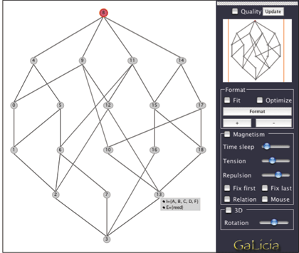
Drawings of concept lattices provide the most common mechanism for the communication of structure extracted from data via the process of formal concept analysis [4]. A common graph drawing approach to the layout of a partially ordered set of which lattices are a sub-class is via a layered diagram. The layered approach consists in assigning each vertex to a horizontal layer and ordering each vertex within a layer in order to reduce edge crossings. Crossing reduction is important for the aesthetic result of the diagram but is unfortunately known to be NP-complete in the graph drawing field, because for each layer, all possible vertices order combinations have to be considered [2].
Figure 1: Layered diagram of a concept lattice and layout parameters.
Diagram Layout
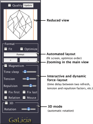
Galicia provides a useful interface to manipulate and lay out concept lattices. Figure 1 shows the main interface to control the layout of the diagram. Different scales can be used and a reduced view shows the entire lattice. Each concept can be moved in the two dimension space and also intent and extent can be displayed. For the layout, it uses a longest path layering to determine the vertical positioning of concepts and provides two interactive methods to assign the horizontal placement of concepts.
Automated layout
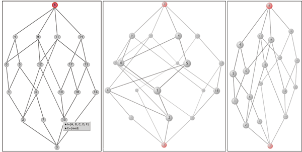
The first method is automated: concepts are ordering by considering for each layer all vertices pairs and counting the number of crossing edges. If a permutation of the two vertices produces less crossings, their respective positions are switched. The process is recursively repeated from the top to the bottom of the lattice and from bottom to top, until the number of crossing stay unchanged. This method is non-optimal because, for each layer, all possible combinations of subsets are not considered. It also gives aesthetic results as showed in figure 3a and illustrated in [2].
Interactive force-layout
The second method is an interactive force-layout approach inspired from the idea of the magnetism. Vertices are pushed back each other and simultaneously attracted by their edges. This attraction factor is computed by minimizing for each vertex the length of the edges. User can interact with the both tension and repulsion parameters to dynamically display the new diagram. Edges can also be repulsive to avoid the unaesthetic effect of edge crossing vertices. To do so, at each cross-level edges, invisible repulsive objects are attached at the vertical of each crossing layer (see Figure 3a).
3D
Diagram results can be displayed in two or three dimension and the automated and force-layout methods applied in the both modes (3a and 3c). For the 3D mode, a 3D-lattice model is built by mapping each vertex on a 3D sphere: extrema of the lattice are assigned on the pole of the sphere and other vertices on the latitude corresponding to their respective layer assignment (3b).

Figure 2: Layout control

Figure 3: (a) Force-directed layout (b) 3D mapping sphere layout (c) 3D force-directed layout
| Contact l FAQ l Download l References l Project |
